
Global illumination
The global illumination system described here allows fast calculation of outdoor scene lighting, with light being reflected and absorbed by vegetation and terrain. The word "fast" here means that relatively high-resolution static light grids can be updated for nearby areas as the camera moves, without precalculating them for the whole scene at build time and using a lot of disk space, and that lighting can be efficiently applied to moving objects and to surfaces with specular lighting etc. Also real-time lighting (movement of light sources or obstacles/reflectors) would probably be possible with a lower (but adequate) resolution or some optimization.
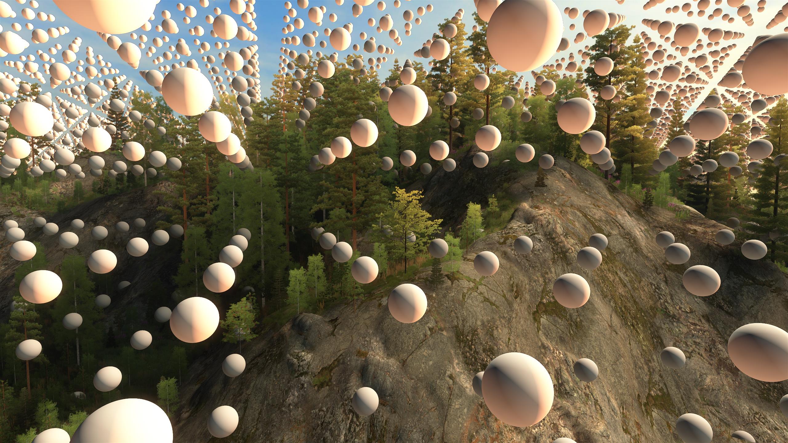
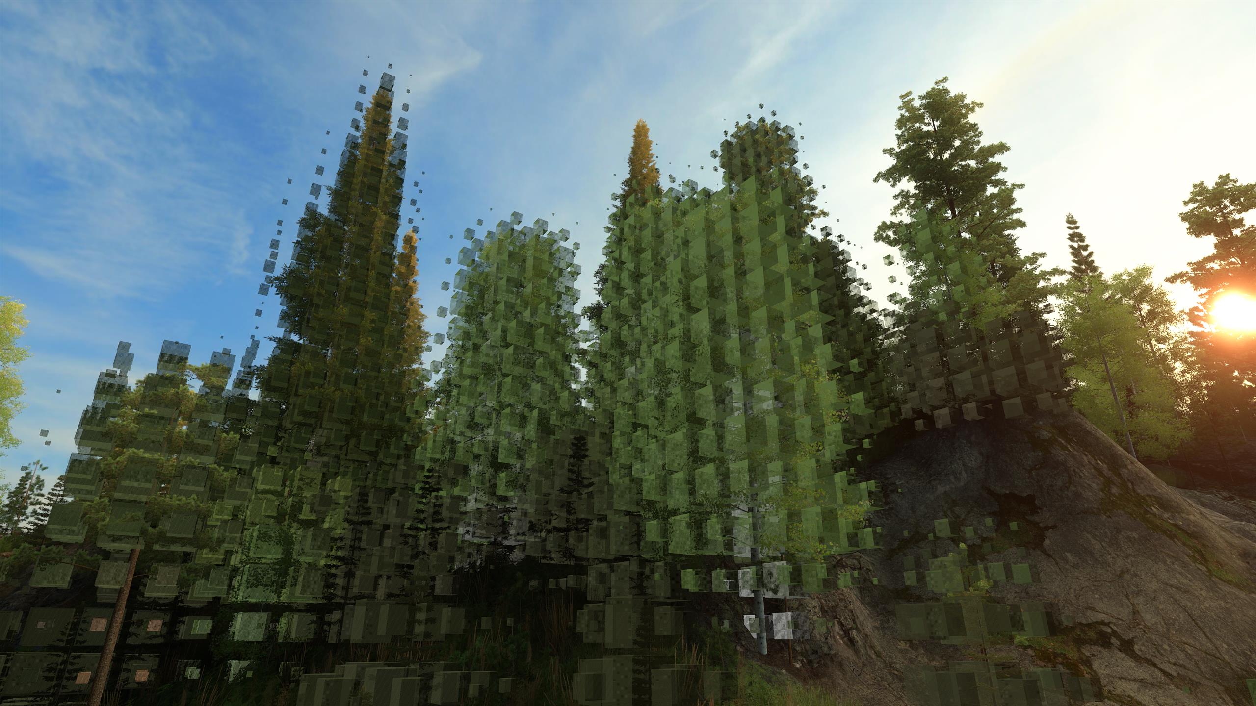
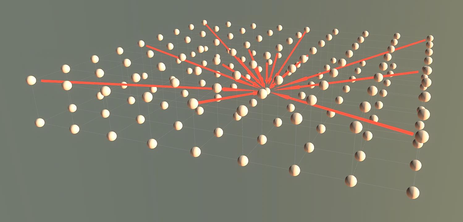
Lighting information is primarily stored in 3D grids, where each grid point contains the intensity and color of incident light in different directions. The grids are updated by tracing light from the sky and calculating how the light gets absorbed and reflected by obstacles. During rendering, lighting at a particular point/vertex is approximated by interpolating between grid points.
The light grids form a hierarchy so that there is one large, low-detail light grid for the entire game world (with 16-meter cell size) and smaller, more accurate light grids for terrain quad tree nodes around the camera (with down to 1-meter cell size).
Update of the lighting information in the grids is done with a top-down sweep algorithm that assumes light flows mostly downwards from the sky, which is suitable for outdoor scenes. The largest grid is updated when the scene is loaded, and smaller grids as the camera moves. This allows better grid resolution than if the entire world's lighting information was precalculated and stored on the disk, because of smaller disk space and precomputation requirements. It also potentially allows more dynamic or even real-time changes to the scene or lighting, although this potential is not currently used.
(click image to zoom)
|
| Light grid cells visualized as white illuminated balls. |
|
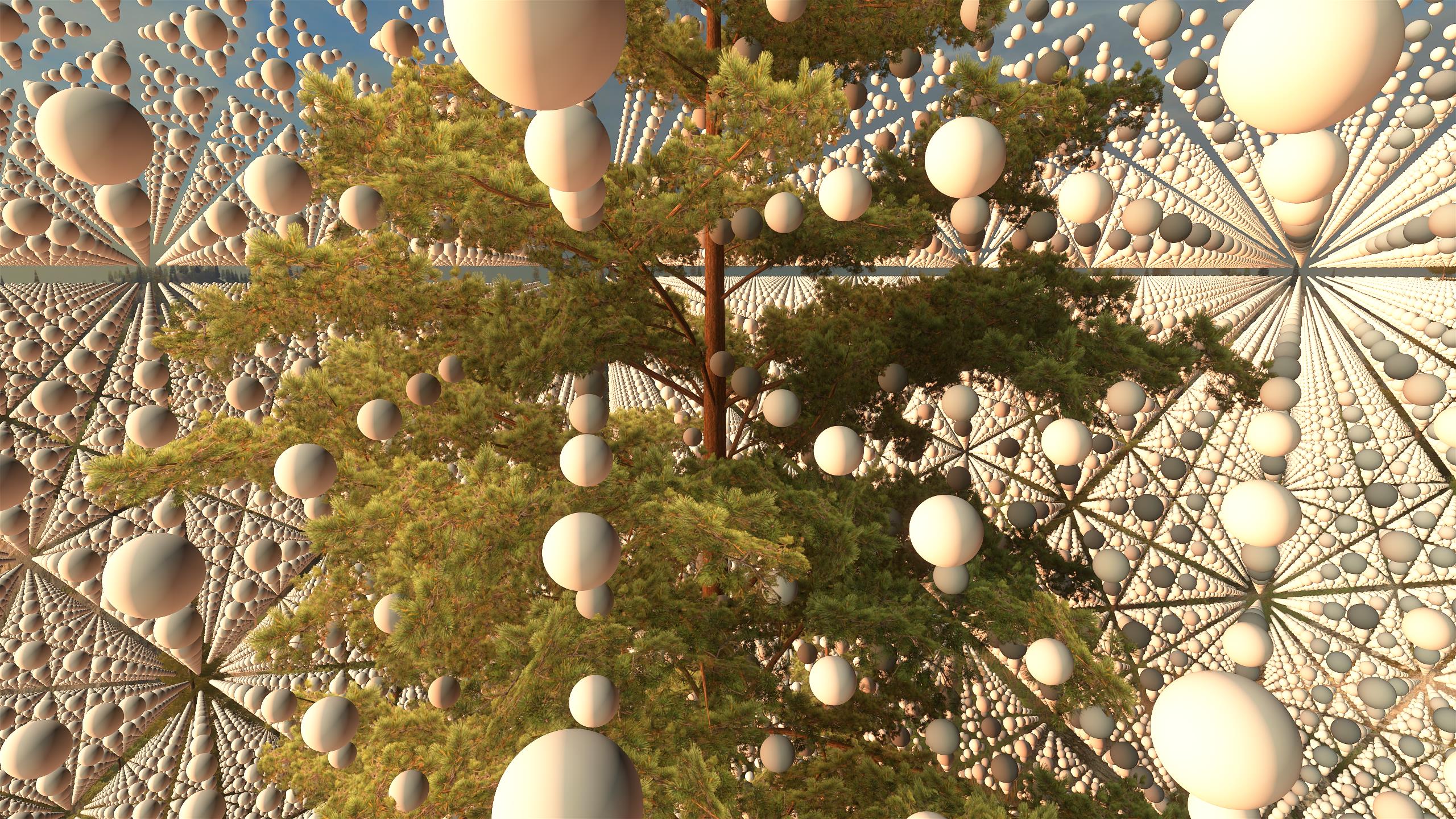
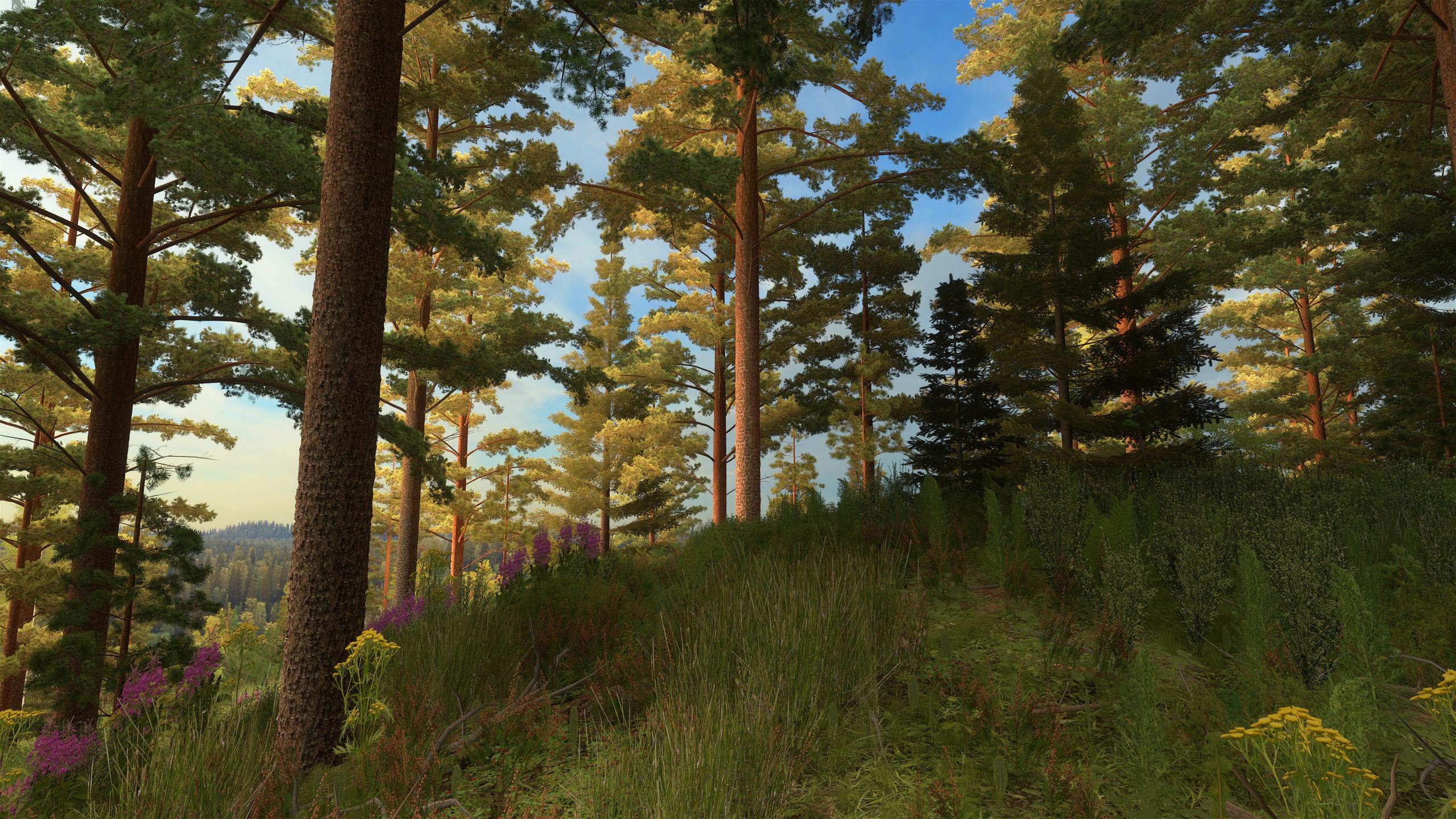
| Tree self-shadowing. |
|
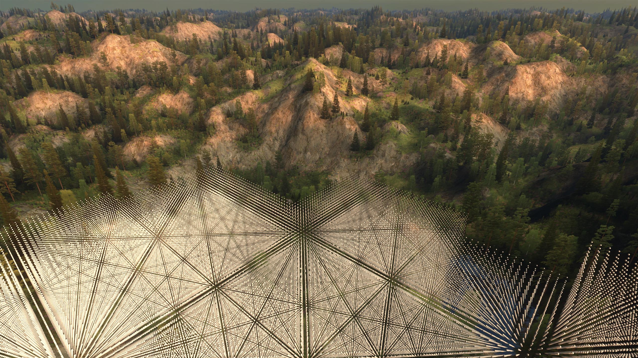
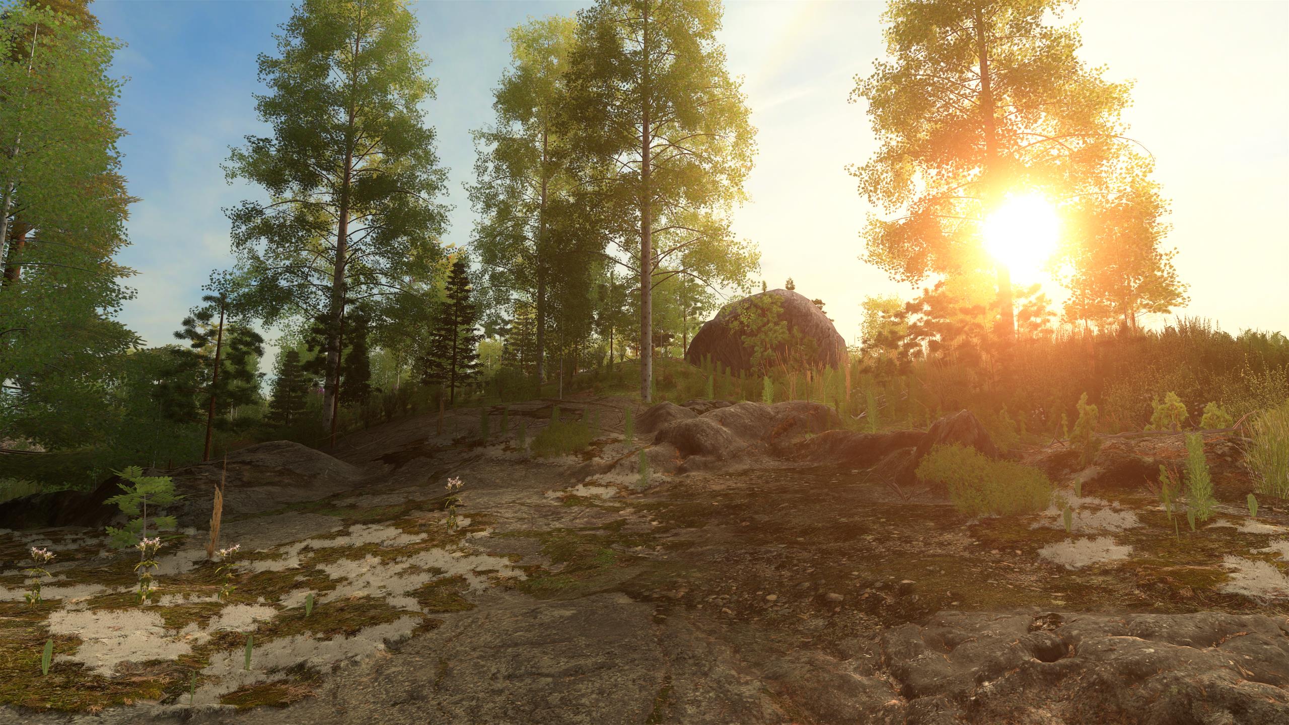
| Light grid nodes with small cell size near the camera. Grid height depends on vegetation height within the terrain node. |
|
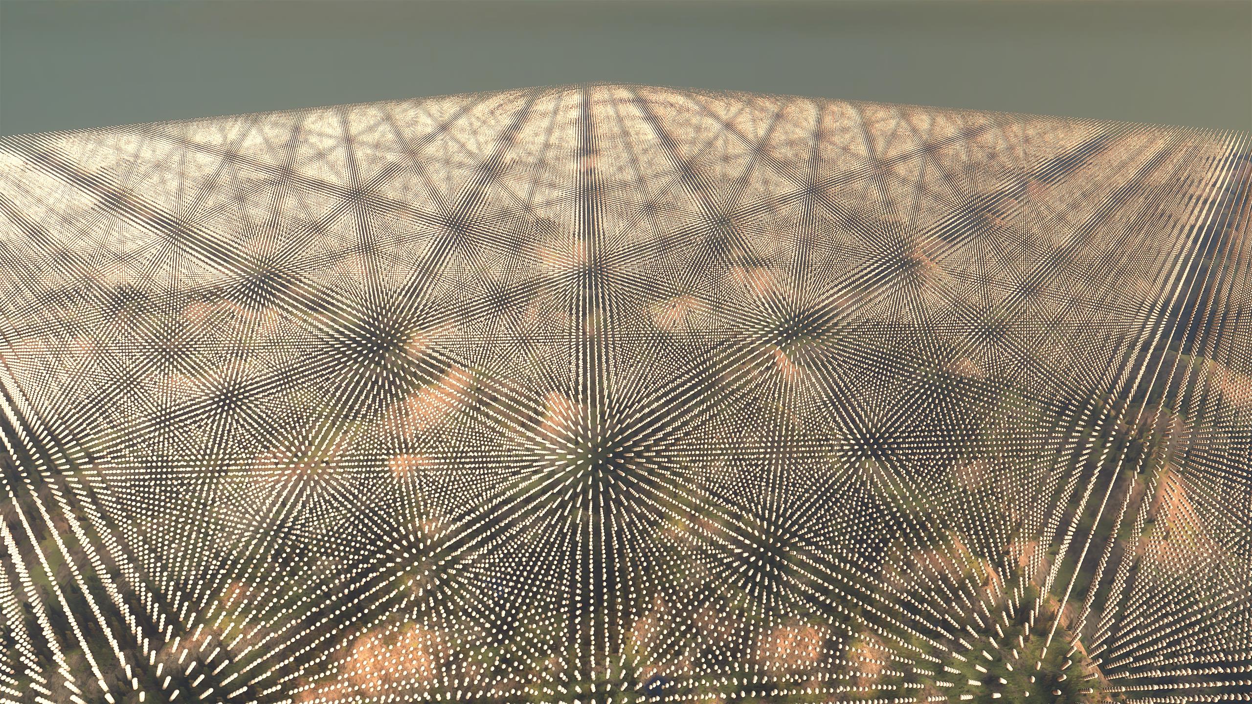
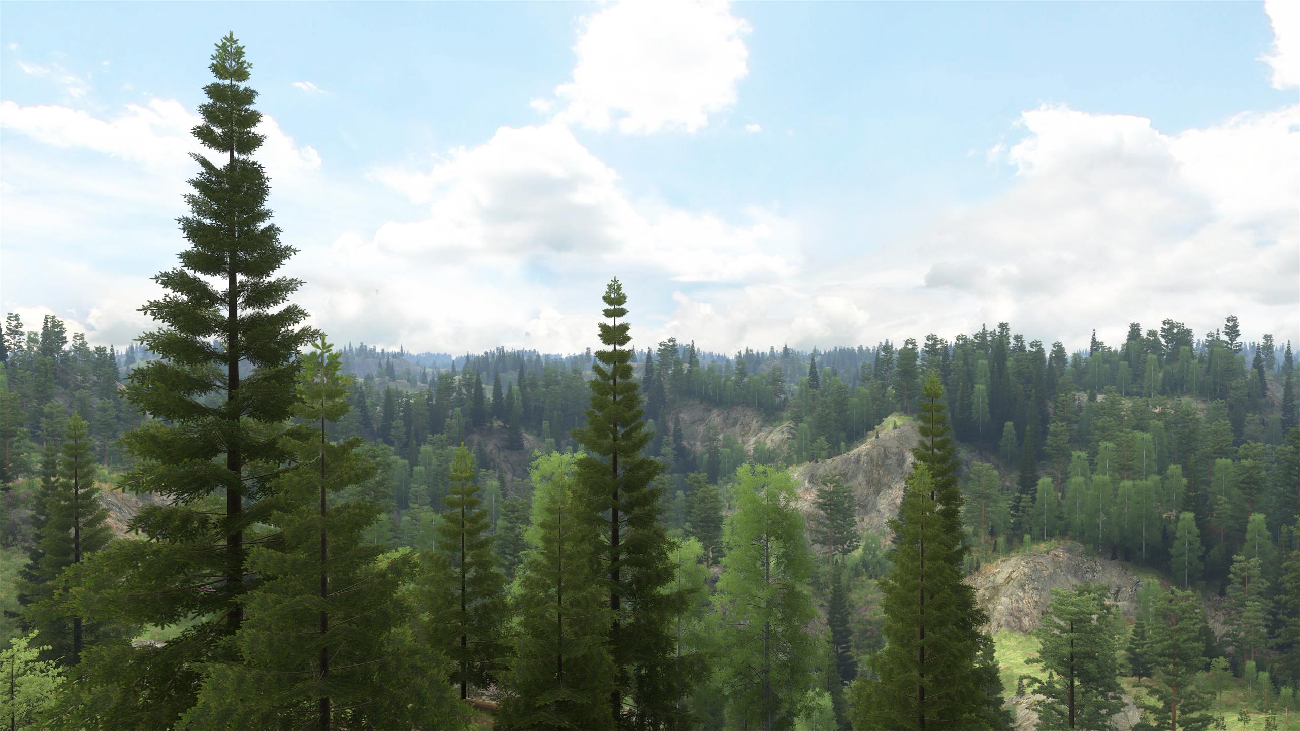
| The largest light grid spans the entire scene. |
Light grid format
Each cell of the light grid stores incident light in 26 directions: each direction along 3D coordinate axes and each diagonal direction. For each direction, the intensity and color of light is specified as HDR RGB values using the R11G11B10 floating-point format. Also the average amount of incident light in all directions in stored in a 3D texture, which can be used for faster lighting calculations when direction information is not needed, e.g. vegetation billboards far away. Another grid is built that contains a vector for each cell that specifies the most dominant light direction, with the length of the vector specifying how sharply the light comes from that direction as opposed to others. This can be used to calculate real-time lighting of objects for which at least approximate directional lighting is preferred, but for which calculating all the 26 directions would be too costly.
Another popular way of storing directional lighting information is by using spherical harmonics, which would be an middle-ground choice in terms of performance and quality between the 26-direction light grid and the dominant-direction grid. In this engine, a dominant-direction grid is used for per-frame lighting (for performance) and a 26-direction grid for non-per-frame lighting (for quality).
Material representation
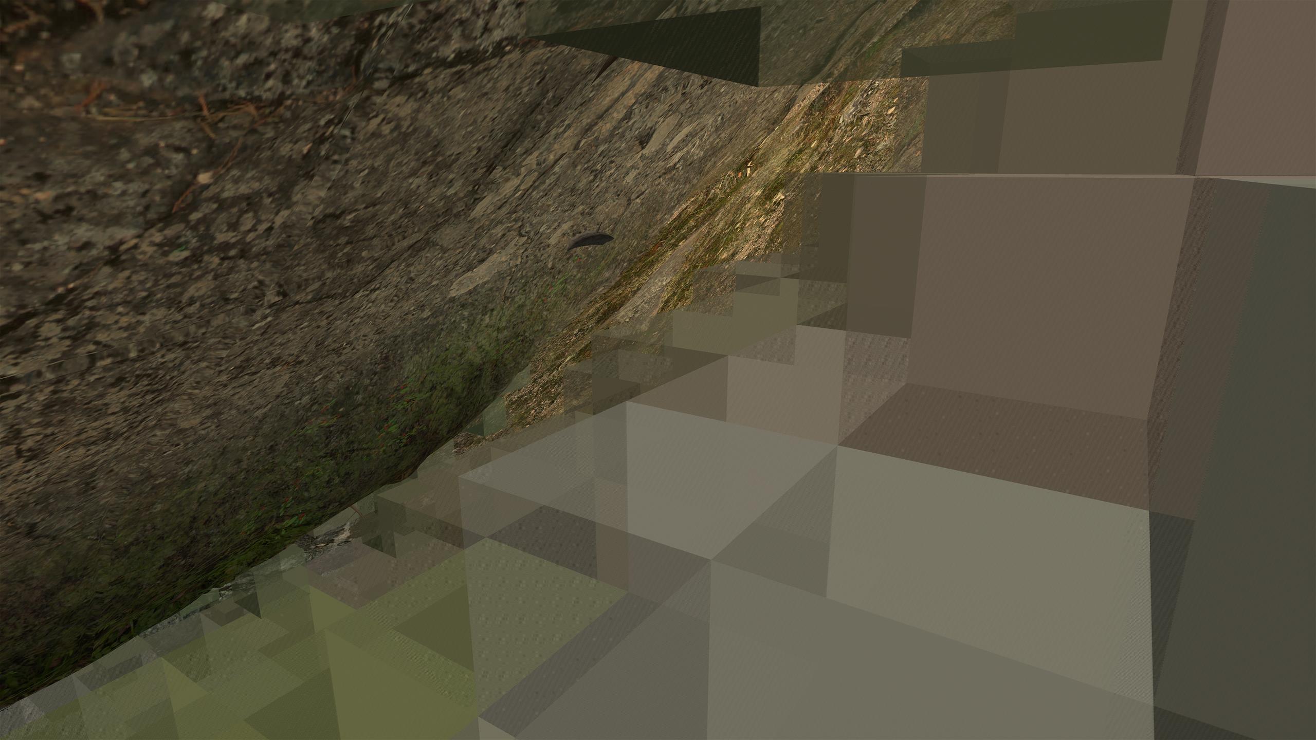
Material that absorbs and reflects light is also represented as 3D grids, where each cell specifies an RGB diffuse reflection factor and a density factor that indicates what proportion of light passes through the cell without getting absorbed.
For each 3D model used in the terrain (trees, rocks etc.), a material grid is generated offline from the geometry and surface material properties. During the game, when a light grid is being updated for an area of terrain, a material grid is formed first for the area, with one cell for each light grid cell. The amount of material in each cell is computed on the GPU by sampling the model material grids according to the positions and orientations of the models (by having a thread per cell and by iterating through CPU-generated linked lists of 3D objects that could affect each thread group).
If a material grid cell is below the ground, then the cell is marked as having full density and the reflection color is read from a ground texture. This is not applied sharply as soon as a cell is just slightly underground, but with a linear transition and a small terrain height bias, to avoid unwanted shadows at hilltops that could result from interpolation errors.
|
| Material color and density in each cell visualized as cubes. Density is represented by cube size. |
|
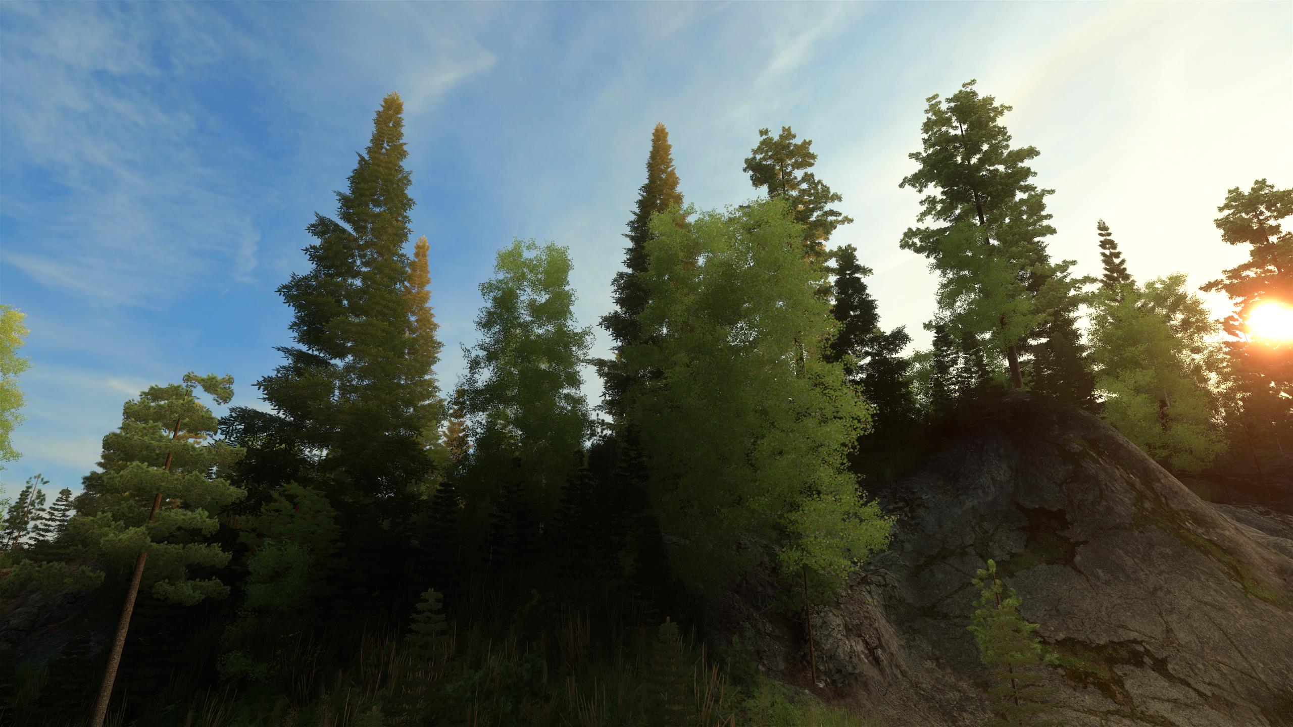
| The previous scene without material cubes. |
|
| Ground material cubes (underground view). |
Tracing light flow, updating the grids
The lowest-detail light grid is updated by first initializing each cell at the topmost level of the grid with light from the sun and the sky, and then tracing the flow of light downwards from each grid point to nearby points, calculating obstructions and reflections. Then the second-lowest-detail grids are updated by initializing the lighting at their edge points with values interpolated from the lowest-detail grid and tracing the flow of light through the grid. This is repeated up to the highest-detail grids.
The iteration is done one horizontal grid level at a time so that the light flows only downwards and sideways, as opposed to updating the entire 3D grid on each iteration with light flowing in all directions, because this is much faster and is a good approximation for outdoor scenes. A second, bottom-to-top pass could be done to compute upward lighting that has reflected off the ground and bushes, but this was not implemented.
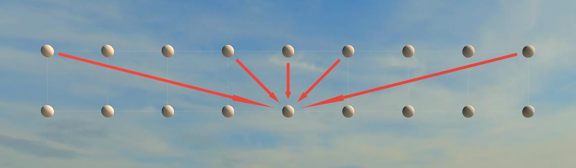
To calculate incident light in a cell, the algorithm processes each of the 17 cells on the previous (upper) level, takes the amount of light that is coming towards the current cell and applies that light to the current cell, taking into account absorption and reflection by material. The 17 directions consist of one straight-down direction, 8 diagonal downward directions (to the 8 neighbor cells of the straight-down cell), and 8 directions where the light moves across 4 cells horizontally while it moves downward one level. This allows simulating downward as well as nearly-horizontal light flow while calculating the lighting one level at a time, and while using only the immediately-previous level as a source when calculating the next level. It also allows using a different data format for intermediate data than for the final light grid, because only one previous level needs to be kept in memory. We can use a ping-pong pair of single-level grids for keeping the current and previous level's lighting data in a high-precision format, while the final light grid could be compressed in a less accurate format, perhaps using spherical harmonics. Furthermore, we can store slightly different data in the temporary grids than the final grid, e.g. use the temporary grids to represent the amount of outgoing light from the cells, which is needed for the next level, and write to the final grid a value that is closer to the average incident light within the cell (that has has traveled only halfway through the cell), because this is a better approximation of the lighting conditions for objects within the cell.
The material grid is queried to decide how much of the incoming light is absorbed and reflected within the current cell. For the nearly-horizontal directions where the light crosses 4 cells sideways, all material grid cells within the path are checked so that the light won't skip through objects. The portion of light that is not absorbed or reflected becomes outgoing light for the current cell, continuing in the same direction that it arrived. The amount of light that passes through in this manner is calculated by simply multiplying the incoming light with the pass-through factor from the material grid. The portion of light that gets diffuse-reflected will change its color according to the reflection RGB factor from the material grid, and is distributed evenly in all outgoing directions, except that for forward directions, the reflected light is also multiplied by the pass-through factor (and for directions between straight-forward and straight-backward, the pass-through factor is interpolated). This is because most of the backward-reflected light is reflected by the front part of the material (typically vegetation) while forward-reflected light passes through all the material within the cell.
In principle, each directional light in each cell on the previous level affects only one cell on the next level. In practice, some smoothing is applied by using a weighted average of the lights of the source cell and its neighbors, because otherwise the fact that the light flow is simulated with a small number of directions would cause inappropriately sharp shadows. Total light energy is preserved by the calculations, except for absorbed light.
Direct sunlight is also handled with this method so that the sun is simply a bright disc in the sky texture. Shadow maps could provide sharper and more detailed shadows for direct sunlight and would be more accurate if the light source or the obstacles were moving, but would cost performance and are not currently used.
|
| Light flow from one level of cells to the next (cross-section). |
|
| Light flow from one level of cells to the next. |
Rendering
Lighting at a particular point/vertex is determined by doing a trilinear interpolation between the 8 corners of the light grid cell around the vertex. The most accurate light grid (smallest cell size) containing the vertex is used, and no special interpolation is done around the edge between a smaller light grid and a larger one, as the small grid's edge points are already initialized with interpolated values from the larger grid.
Vegetation in this game is relatively dense, and to improve performance, the lighting of bushes, leaves and needles is done by only using the average-light grid that does not have direction information. When a terrain LOD quad-tree node is prepared, vertices are collected into a "light sampling buffer" that allows calculating the lighting (interpolating from the light grid) for all of them with one compute call. Vertex shaders then simply read the light color from the sampling buffer. Lighting does not have to be updated on every frame and there does not need to be a one-to-one correspondence between vertices and light sampling points. Self-shadowing within large trees gets handled by having multiple light grid cells within the tree so that cells that are at the back side of the tree become darker.
Stationary surfaces that support diffuse reflections but not specular are also added to a light sampling buffer, with normal vectors included. Their lighting is computed at terrain node preparation time using the 26-direction light grid, which has good quality but would be too heavy for lighting millions of vertices on every frame. For those stationary surfaces that need per-frame and per-pixel lighting with normal/specular maps (e.g. rocks), the lighting is first calculated this way per-vertex, then adjusted in the pixel shader according to the dominant-light-direction grid and the surface normal. This brings the quality of the 26-direction light grid for the overall surface lighting while using the dominant-direction information to cheaply add an approximate specular reflection.
For moving objects and changing lighting conditions, the average-light grid with the dominant-direction grid are fast enough for calculating the lighting per-frame for even millions of vertices, as they are simply 3D texture lookups with trilinear interpolation and have good cache locality.
An additional tweak is used to remove discontinuities of lighting between the ground that uses surface normals and objects near the ground that don't use normals or have normals pointing in different directions than the ground. Especially near the top of hills where the ground should be in shadow, the calculated light might not actually be shadowed due to the limited resolution of the light grid, and the ground would appear dark because it is facing away from the light, while bushes near the ground would appear bright. This is fixed by interpolating the lighting of bushes and other objects so that the closer their vertices are to the ground, the more similar their lighting will be to the ground lighting (e.g. diffuse lighting will appear as if the surface normal of a bush was the same as the ground normal).
Underwater lighting is handled specially by reading water depth from a texture and determining how deep the vertex/point is under water and how quickly the lighting should get darker by water depth (using an exponential curve). Another special case is the flashlight that simply increases the light at the front of the camera using an empirical formula, without producing shadows.
Performance
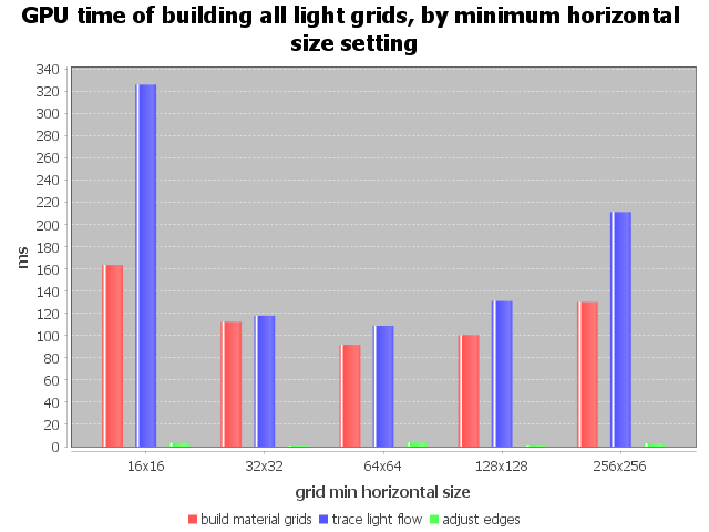
Below are performance figures from updating all light grids in the scene, measured on an Nvidia GeForce GTX 980 Ti. The "grid min horizontal size setting" is approximately the light grid size in x,z directions (can be slightly larger because vegetation in a terrain quad tree node may extend slightly outside the node). The full operation is done only once after the scene has been loaded, and is easily fast enough for that. As the camera moves, new light grids are prepared individually and over several frames to make the GPU time insignificant. Real-time per-frame update of all light grids would probably be possible but would need optimizations, e.g. using a cascade light grid hierarchy around the camera instead of having a light grid per terrain node, to remove overlap among grids of the same resolution.
Due to the test results, light grid min size was configured to 32x32 for optimum performance and memory usage. The light grids are built one horizontal level per compute call, so a level size of 32x32 or 64x64 is sufficient for good GPU occupancy, while it avoids having too detailed grids too far away and may have better cache locality than larger grids.
|
| How much GPU time it takes to build all light grids in the scene, depending on light grid size configuration. |
|
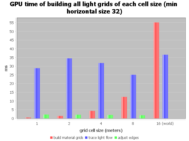
| How much GPU time it takes to build all light grids of each cell size. The grid with cell size 16 covers the entire world and is much larger than the other grids. Larger grids also contain larger numbers of terrain objects, which affects the material grid build time. |
|
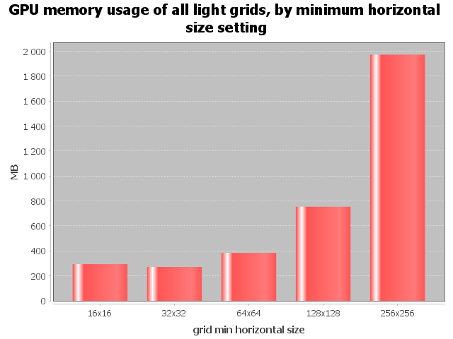
| If a larger grid size is used, the grids will have more detailed resolution further away from the camera, increasing memory usage. Too small grid sizes would waste memory because of overlap at terrain quad tree node margins (only slightly with size 16x16). The 26-direction grids take up most of the memory, which could be optimized by e.g. spherical harmonics. |

|
| The compute call overhead was small in this test and the CPU time needed was only about 10% of the GPU time. The number of compute calls also equals the number of horizontal light grid levels, as one compute call is made per level. |